Why Boat Fuel Gauges Fail in the First Place
Boat fuel gauges have gotten complicated with all the misinformation flying around. People replace gauges, rewire entire helm panels, call in marine technicians — when the actual culprit is usually a $40 sender unit that’s been sitting corroded on top of the tank for three seasons. I learned this the hard way. Spent about three hours one Saturday chasing what I was convinced was a fuel delivery problem on my 28-foot center console, tearing apart the bilge area, convinced something was catastrophically wrong. It wasn’t.
Boat fuel gauge systems are, honestly, refreshingly simple. Three components. Three failure points. That’s the whole puzzle.
- The sender unit (inside the fuel tank) — the most common failure point by a huge margin
- The wiring between the sender and the gauge — usually corrosion or a loose ground somewhere
- The gauge itself — least likely to be your problem, but the most expensive thing to replace
The sender unit is a variable resistor — it floats directly on your fuel. Float arm rises, resistance changes, that signal travels through a single wire to your gauge, needle moves. Simple. But stick that float arm in a saltwater environment for a few years and it corrodes, binds up, or snaps entirely. That’s what makes sender units the usual suspect here. They’re just doing a hard job in a brutal environment.
Test in this exact order. Sender first, wiring second, gauge last. The sender costs under a hundred bucks and fails constantly. The gauge costs $200–600 and almost never fails. Don’t make my mistake of starting at the expensive end.
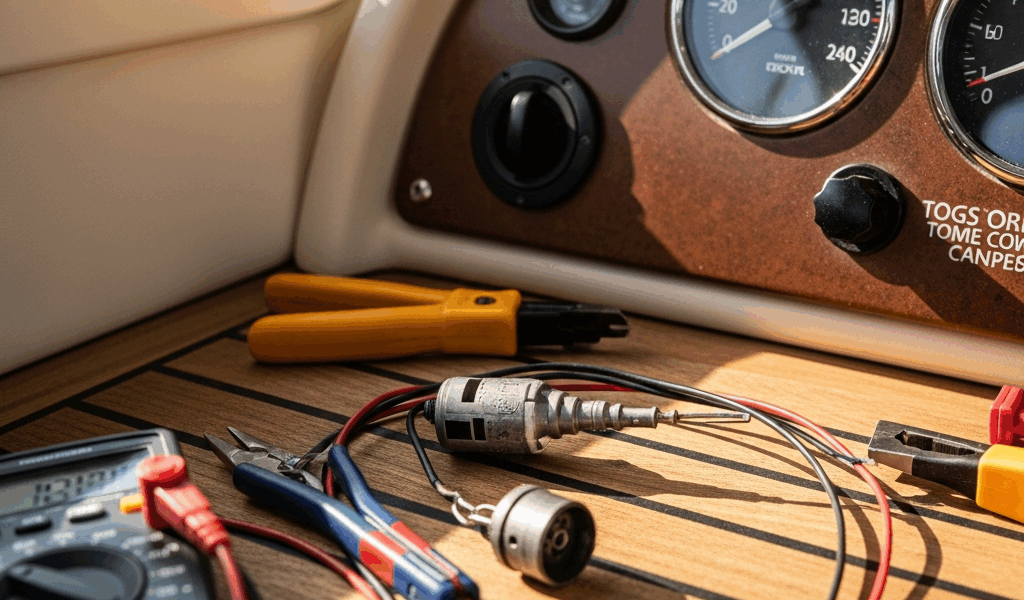
What You Need Before You Start
Probably should have opened with this section, honestly. Good news though — you don’t need specialized marine equipment or a technician standing over your shoulder for any of this.
Grab these items:
- A digital multimeter — $15 to $40 at any hardware store, a Fluke 101 works fine
- Basic hand tools — a crescent wrench, flathead and Phillips screwdrivers
- Your boat’s wiring diagram, if you can track one down
- Electrical contact cleaner and a clean rag
- Paper and pen to log your resistance readings
That’s it. You’re not rebuilding anything. You’re reading electrical resistance values and checking continuity — two skills a multimeter handles completely on its own. The diagnostic work here is slow and methodical, not technically difficult.
Step-by-Step Diagnosis Starting With the Sender
Start here because the sender fails more often than the other two components combined.
Locate your sender unit. It bolts directly to the top of the fuel tank — look for a cylindrical metal housing with wiring running out of it, usually accessible from the cabin or bilge. On my boat it was tucked under the deck just aft of the helm. Took me ten minutes to find it the first time. Your wiring diagram will show the exact position if you’re searching blind.
Disconnect the signal wire from the sender terminal before doing anything else. It’s typically a spade connector or a bolt connection — single wire, carrying resistance signal toward the gauge. Write down which wire connects where. Seriously, write it down.
With the signal wire disconnected, ground the sender body directly to your negative battery terminal using a temporary jumper clip. Turn on the ignition. Watch the gauge. Did the needle swing to full? That means your gauge and downstream wiring are both working — the only component you just bypassed was the sender itself. Bad sender. That’s your answer.
But let’s say the gauge didn’t move at all. Reconnect that wire and grab your multimeter.
Set the multimeter to resistance — ohms. Touch probes to the sender terminal and a solid ground point on the sender housing. Standard US marine senders read roughly 33 ohms at full and 240 ohms at empty — though your specific boat’s documentation should list the exact spec. Write down whatever you’re seeing.
Now rock the sender gently side to side. Tap it. If that resistance reading jumps erratically or stays frozen at one number regardless of movement, the float arm is stuck or broken. That’s your problem. Replace the sender. If readings move smoothly between 33 and 240 ohms, move to the wiring.
How to Check the Wiring Between Sender and Gauge
This section catches a lot of people because they assume the wiring is fine. It’s not — at least not if your boat has spent any real time on saltwater. Corrosion works fast and quiet.
Run a continuity test on the signal wire. Sender still disconnected, multimeter in continuity mode. One probe on the sender terminal, the other on the gauge terminal inside the cabin where that same wire connects. A solid connection beeps and shows near-zero ohms. Silence and infinite resistance means the wire is broken or pulled loose somewhere along the run.
Check the ground at the sender. I’m apparently someone who ignored this for two full seasons and a loose ground caused every weird reading I ever got — and re-seating that connection fixed everything. The sender needs both a signal wire and a return ground path to the negative battery. Find the ground bolt on the sender housing. Is it corroded? Green or white buildup around it? Clean it, tighten it. This single step solves more false fuel gauge readings than anything else on this list.
If continuity passes but the gauge still reads wrong, you’re probably dealing with high-resistance corrosion — not a complete break, just enough buildup to slow and distort the signal. Walk every connector along that wire run. Pull them apart. Clean terminals with electrical contact cleaner and fine sandpaper if you spot any oxidation. Reconnect hand-tight first, then snug with a wrench.
When the Gauge Itself Is the Problem
If the sender reads correctly and the wiring has clean continuity — the gauge is your problem. Also the most expensive repair you’ll make. Replacement gauges typically run $200 to $600 depending on make and model.
Test the gauge with a known resistance value. You’ll need a fixed resistor or a resistance decade box — the decade box runs about $30 and gives you adjustable resistance values. Disconnect the signal wire from the gauge terminal. Connect the resistor or box in its place. Set it to 33 ohms. Needle should swing to full. Dial up to 240 ohms. Needle should drop to empty.
No movement at all means the gauge is dead. Movement that’s erratic or stops at the wrong positions means the internal mechanism is out of calibration. Either way, you’re ordering a replacement.
Order a gauge that matches your sender’s resistance range. This matters more than people realize. A gauge calibrated for a 0–90 ohm sender will not read accurately with a 33–240 ohm sender — the needle will be wrong at every point on the dial. Check the parts documentation before you buy anything.
Installation is usually three bolts and one signal wire — but it does mean pulling your instrument cluster out. Give yourself a free afternoon, take photos before you disconnect anything, and label every wire.
Sender first. Wiring second. Gauge last. Follow the sequence and you’ll find the problem without spending money guessing.


Stay in the loop
Get the latest nautical soundings updates delivered to your inbox.